Welcome to Our Factory for a Visit! Free customized disinfection solutions

In drinking-water plants that use chlorine dioxide for disinfection, the generation, transfer, and dosing system is an important part of stable disinfection operation.
During long-term operation, some plants may encounter white, yellowish-white, or other deposits in dosing lines, valves, flowmeters, and injection assemblies. As the deposits accumulate, flow can decrease, metering can become unstable, and valves may begin to malfunction. In severe cases, stable chlorine dioxide dosing may be affected.
What are these deposits? Why do they form, and how should they be prevented and removed?
The most reliable solution is not simply to “unblock the line” or increase pressure. The entire system—including generator performance, chemical quality, piping design, injection-point conditions, and maintenance practices—should be evaluated.
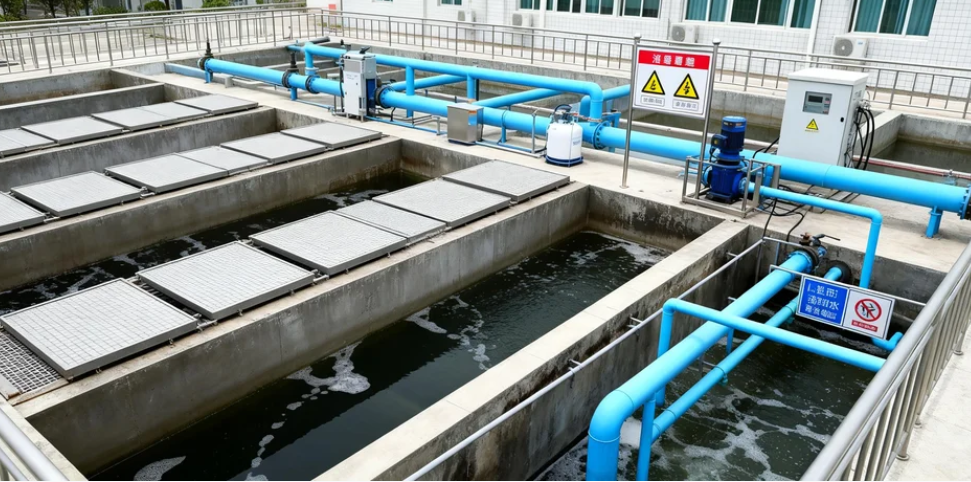
It is too simplistic to assume that every white or yellowish deposit in a chlorine dioxide dosing line is crystallized chlorite or chlorate formed by disproportionation of chlorine dioxide.
Chlorine dioxide can undergo decomposition or transformation depending on light exposure, temperature, pH, and water chemistry, producing chlorite, chlorate, and other species. However, whether these compounds form visible hard deposits depends on solution composition, concentration, evaporation, temperature, and the presence of other ions.
Deposits in a chlorine dioxide system may have several sources. Incomplete generator reactions can leave residual feed chemicals or salts. High local concentrations and long stagnant periods may cause salts to concentrate and crystallize. Hard water may contribute calcium- or magnesium-based scale, while iron and manganese can produce oxide deposits.
When the same line repeatedly blocks, a more reliable approach is to collect a small sample of the deposit and analyze its composition while also reviewing chemical-feed conditions, generator performance, line flow, temperature, and injection-point design.
Only after determining whether the deposit is salt crystallization, hardness scale, iron/manganese oxide, or another material should a specific cleaning method be selected.
Blockage should also not automatically be blamed on poor maintenance. In many systems, it results from a combination of operating conditions, reaction efficiency, water quality, piping geometry, and maintenance practices.
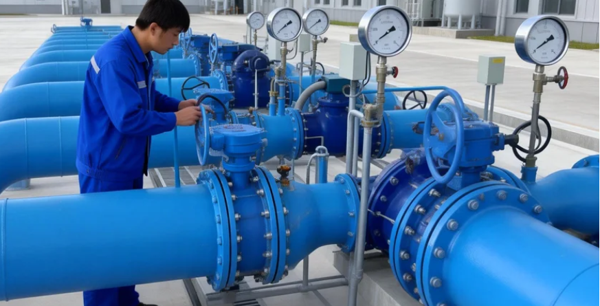
Preventing blockage requires more than a single measure. It should be managed throughout chlorine dioxide generation, transfer, injection, flushing, and maintenance.
Blockage prevention begins with the generator itself.
Whether the system uses a chlorate-based or chlorite-based process, feed chemicals should meet the specifications required by the equipment manufacturer, and concentration, dosing ratio, and flow should remain within the validated operating range.
The objective is not simply to achieve the “highest possible chlorine dioxide purity,” but to maintain stable conversion efficiency and minimize abnormal residual feed chemicals and by-products.
Where appropriate analytical capability exists, operators may trend chlorine dioxide concentration, chlorite, chlorate, raw-material consumption, and other indicators relevant to the specific generator chemistry.
Stable generation, qualified feed chemicals, and reliable metering provide the first line of defense against abnormal deposits.
The main objective of the dosing line is to transfer chlorine dioxide solution to the injection point through a stable and reasonably short path while minimizing dead legs, stagnant pockets, and backflow.
The line should not be made unnecessarily long, but it should still allow safe pressure control, maintenance, and inspection.
Valve selection should not be reduced to a rule that ball and globe valves are always unacceptable while diaphragm and butterfly valves are always preferred.
In small chemical dosing systems, diaphragm valves, compatible check valves, and back-pressure valves are commonly used. Full-port ball valves may also be suitable in some applications.
The main objective is to avoid configurations that trap chemical solution or cannot be completely drained and flushed.
Flow velocity should also not be universally fixed above 1.5 m/s. Whether flow is laminar or turbulent depends on pipe diameter, flow rate, fluid properties, and Reynolds number. Excessive velocity can also increase pressure loss and equipment loading.
An appropriate velocity should therefore be established from the actual design flow and pipe diameter, with particular attention to avoiding long periods of stagnation or very low flow.
Material compatibility must also be evaluated under the actual chlorine dioxide concentration, temperature, pH, chloride level, and exposure time.
PTFE and some grades of CPVC are chemically resistant in many chlorine dioxide applications, but manufacturer compatibility data should still be checked. 316L stainless steel should not automatically be described as universally suitable, particularly at higher oxidant concentrations, higher temperatures, or in chloride-containing environments.
For intermittently operated lines or injection points where local concentration can increase, an appropriate flushing program is often valuable.
After dosing stops, clean water or suitably treated water may be used—where the system design allows—to displace residual chemical solution and reduce the risk of concentration, decomposition, or crystallization during extended stagnation.
Continuous low-flow carrier water, however, is not suitable for every system. Poorly designed carrier-water systems can affect actual dosing concentration, metering accuracy, or create backflow risks.
The flushing arrangement should therefore include appropriate check protection, interlocks, and a defined discharge route and should be commissioned to ensure that it does not interfere with normal dosing.
The original recommendation to keep every dosing line above 15°C requires correction.
Low temperature may affect the solubility of certain salts, but chlorine dioxide itself can decompose and off-gas more rapidly when exposed to excessive heat.
In cold climates, the priority should be freeze protection in accordance with equipment-manufacturer requirements.
At the same time, product solution and piping should be protected from direct sunlight and excessive heating.
Whether insulation or heat tracing is needed, and what temperature range should be maintained, should be determined according to the generator chemistry, equipment design, and manufacturer specifications rather than a universal 15°C rule.
Effective blockage prevention should shift from reactive cleaning to trend-based maintenance.
Routine inspection should include changes in dosing flow, metering-pump discharge pressure, flowmeter stability, valve performance, and visible deposits around injection points or transparent sections.
Where appropriate, flow, pressure, or differential-pressure trends can help identify increasing hydraulic resistance. However, rising pressure alone does not prove blockage because valve position, back pressure, and downstream water pressure can also affect readings.
Preventive cleaning frequency should not be fixed at “every quarter” or “every six months.” It should be based on actual fouling rate, pressure and flow trends, shutdown frequency, and equipment-manufacturer guidance.
Most importantly, a chemical cleaner should not be selected until the nature of the deposit is understood.
Sodium bisulfate is an acidic salt rather than a general reducing agent. If sodium bisulfite was intended, that is a different chemical altogether. Hydrogen peroxide can also behave differently depending on reaction conditions and should not be treated as a universal cleaner for chlorine dioxide systems.
A safer maintenance approach is to stop generation and dosing, isolate the affected section, thoroughly flush and displace residual chemicals, confirm that hazardous chlorine dioxide concentrations and active feedstocks are no longer present, and then select an appropriate cleaning method based on deposit analysis and manufacturer recommendations.
If chlorite, chlorate, or other oxidizing residues may still be present, strong acids such as hydrochloric acid should never be introduced without a formal risk assessment because acidification of certain chlorine-oxygen systems can generate hazardous chlorine dioxide or chlorine gas.
Chemical cleaning should therefore follow a simple principle: identify the deposit first, confirm material and chemical compatibility second, and only then develop the cleaning procedure.
Critical components such as flowmeters, check valves, diaphragms, and injection valves may be stocked as appropriate spare parts, and the plant should establish a safe shutdown, flushing, inspection, and restart procedure.
Preventing blockage in a chlorine dioxide dosing system is a system-engineering task. It begins with generator conditions, raw-material quality, and conversion efficiency and continues through piping geometry, valves, flushing design, temperature management, and routine maintenance.
The most effective approach is not to memorize fixed numbers such as “1.5 m/s flow velocity,” “15°C minimum temperature,” or “clean every six months.” It is to identify the actual deposit mechanism in the specific plant and establish control parameters that reflect real system behavior.
Every water treatment plant has different water quality, generator chemistry, chemical concentration, pipe diameter, flow, and operating pattern. Continuous observation, analysis, and optimization are therefore necessary to develop a truly effective anti-blockage strategy.
Chlorine dioxide disinfection pipelines in water plants are prone to blockage due to salt crystallization caused by disproportionation reactions. This can be prevented by optimizing the purity of the solution, designing the pipeline properly, regularly flushing and insulating, and conducting thorough inspections and chemical cleaning (hydrochloric acid should not be used). These multi-dimensional measures can help prevent crystallization and ensure the stable operation of the disinfection system.
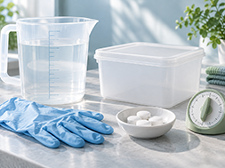
The pestis pestis leakage incident in the Russian laboratory reminded the public that pestis can be spread by fleas, infected animals, and droplets. The prevention and control should focus on the environment and rat flea management, instead of blind disinfection and sterilization. Xiuba chlorine dioxide disinfection tablet can only be used for preventive disinfection of object surface according to instructions. It has no special killing effect of pestis bacilli, and cannot be used as special epidemic prevention materials for pestis. It needs to be operated in a standardized way. Do not over disinfect due to network rumors.
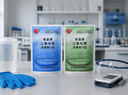
In 2026, Xiuba proposed that it is not enough to simply meet product qualification requirements; it is necessary to promote "green" practices in product selection, operation, safety, and record-keeping, rely on actual measurement data to verify effectiveness, strictly adhere to safety boundaries, and promote high-quality development of the industry.
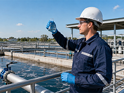
Traditional chlorine preparations are prone to producing harmful chlorination by-products and will eventually be phased out; Chlorine dioxide relies on a unique electron transfer oxidation mechanism, producing almost no organic chlorides, with high sterilization efficiency and lower risk of by-products. Xiuba relies on years of large-scale production and university research cooperation, with complete product qualifications, strict control of disinfection residues, and a balance between effective disinfection and ecological green, in line with the industry's green and low-carbon development trend.

Focusing on three core selection dimensions—cost, safety, and broad-spectrum disinfection—this article compares chlorine dioxide with disinfectants such as ozone and peracetic acid, highlighting its significant advantages in terms of sterilization mechanism, usage safety, and long-term cost. The product is suitable for various scenarios including water supply, food processing, and wastewater treatment. Addressing market issues of misleading labeling, the article provides purchasing advice and recommends Xiuba Chlorine Dioxide, a brand with deep industry experience and complete certifications.
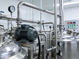
This article points out that during CIP cleaning, adding chlorine dioxide before alkaline washing and during acid-alkali rinsing has poor effects; the optimal point is after acid washing, when the acidic clean environment is suitable for the agent, and it is also necessary to drain residual acid, control the temperature, and circulate for 15-20 minutes to improve the disinfection effect.
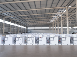
This article compares the applicable scenarios of chemical and electrolytic chlorine dioxide generators, explaining the manufacturer selection criteria from five dimensions: qualifications, accessories, case studies, after-sales service, and process compatibility. It also introduces five major development trends, including intelligent and modular equipment. Xiuba XB series equipment complies with GB 28931-2024 standards, has complete qualifications, and offers 24/7 full-process service. It is suitable for multiple industries and can reduce maintenance costs and operational risks.
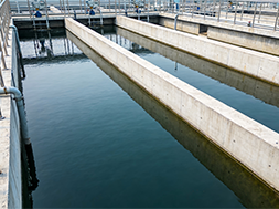
Chlorine dioxide is safe, efficient, and suitable for multiple industries, with the market continuously expanding and benefiting from ongoing policy support.Shandong Huashi Pharmaceutical's Xiuba division has been deeply involved in the industry for many years and can provide a full range of chlorine dioxide disinfection products and related technical services.
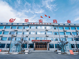
Xiuba has been deeply involved in chlorine dioxide disinfection for nearly 30 years, possessing mature technology and a rich product line. The brand has completed a strategic transformation, shifting from simply selling products to providing customized disinfection services throughout the entire process, integrating industry resources, and specifically addressing various disinfection pain points for companies in the drinking water, food, and medical fields.
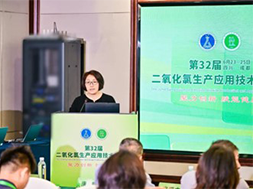
Shandong Huashi Pharmaceutical took part in the 32nd National Chlorine Dioxide Technology Symposium held in Chengdu this June. Our technical team shared professional research on chlorine dioxide disinfection for medical and public health scenarios and exchanged industry technologies with over 70 experts and manufacturers. This participation fully proves our solid R&D strength and professional standing in the chlorine dioxide disinfection field.
Northeast of Huangshan Road and Chuangye Intersection, Small and Medium sized Enterprise Entrepreneurship Industrial Park, Shanwang Town, Linqu County, Weifang City, Shandong Province
Copyright © 2025 by Shandong Huashi Pharmaceutical Co., Ltd All Rights Reserved


 Language
 中文
中文 Русский
 Chlorine Dioxide Disinfectant Manufacturer


